|
Pittler Lathe model
|
|
Some notes on the construction
|
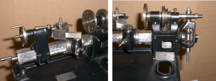
| Several years ago I had in the workshop a full size Pittler B2 lathe, this lathe was supplied originally by Geo. Adams around 1910 & was a state of the art piece of kit at the time, very expensive in comparison to other similar sized lathes on the market, this probably accounts for the fact that there are so few still knocking around especially complete with all the gears. A very versatile machine with the ability for plain turning with auto feed & auto stop, screw cutting, gear cutting including bevels & spirals (with overhead gear). (For full account of the capabilities see the Geo. Gentry articles in Model Engineer Magazine, Vols. 82 & 84)
I was looking after this for someone while they decided what to do with it (It was subsequently sold). Mooching around the workshop one day trying to decide what to do, the Pittler caught my eye and I decided that it would make an excellent model at ¼ scale. With the original in the workshop it was a straightforward exercise to produce the necessary dimensions, it was simply a matter of taking a bit off the original, measuring & dividing by 4. As with any new project the first thing is to decide if the materials are readily available without the expenditure too much beer money. |
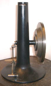 |
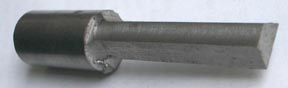
The majority of the parts for the model are quite small so this was not a problem, however the main pedestal is fairly substantial and required either a casting with the attendant requirement for a pattern etc., an 8” length of 3” bar (which would then produce more swarf than the bin men would tolerate) or some ‘lumps’ for fabrication. A dig in the scrap box produced an 1” thick steel disc of a suitable diameter and a length of 2” bar stock. The bar was turned down on the end to form a spigot & the disc bored for a shrink fit. The disc went in the oven & the bar in the freezer, when suitably hot and cold the two were offered up and pressed together, unfortunately I was not quick enough & the heat transfer beat me to it !. However, a hefty smack with my late grandfather’s trusty 7 lb., sledge persuaded the bits to go together properly. The ‘lumps’ now one ‘lump’ was machined on the Myford, I had made the Hemingway taper turning attachment some time before so the taper section was easy, the rest was roughed out with a round-nose tool & finally finished to profile by hand turning. The flywheel was a straight turning exercise. The groove in the largest diameter is for the overhead gear, that in the small diameter was for an accessory which drove the lead screw independent of the head stock (eg for cutting spirals with the overhead gear) |
The little wooden drawer is made from holly, a nice hard, fine grained wood. The joints are halved and making them nearly lost me a finger ! I used the milling machine like an upside down spindle moulder with a sharp new cutter, however, feeding the little bits of wood through, I took my eye off the ball & you can guess the rest.
| Back |